About Course
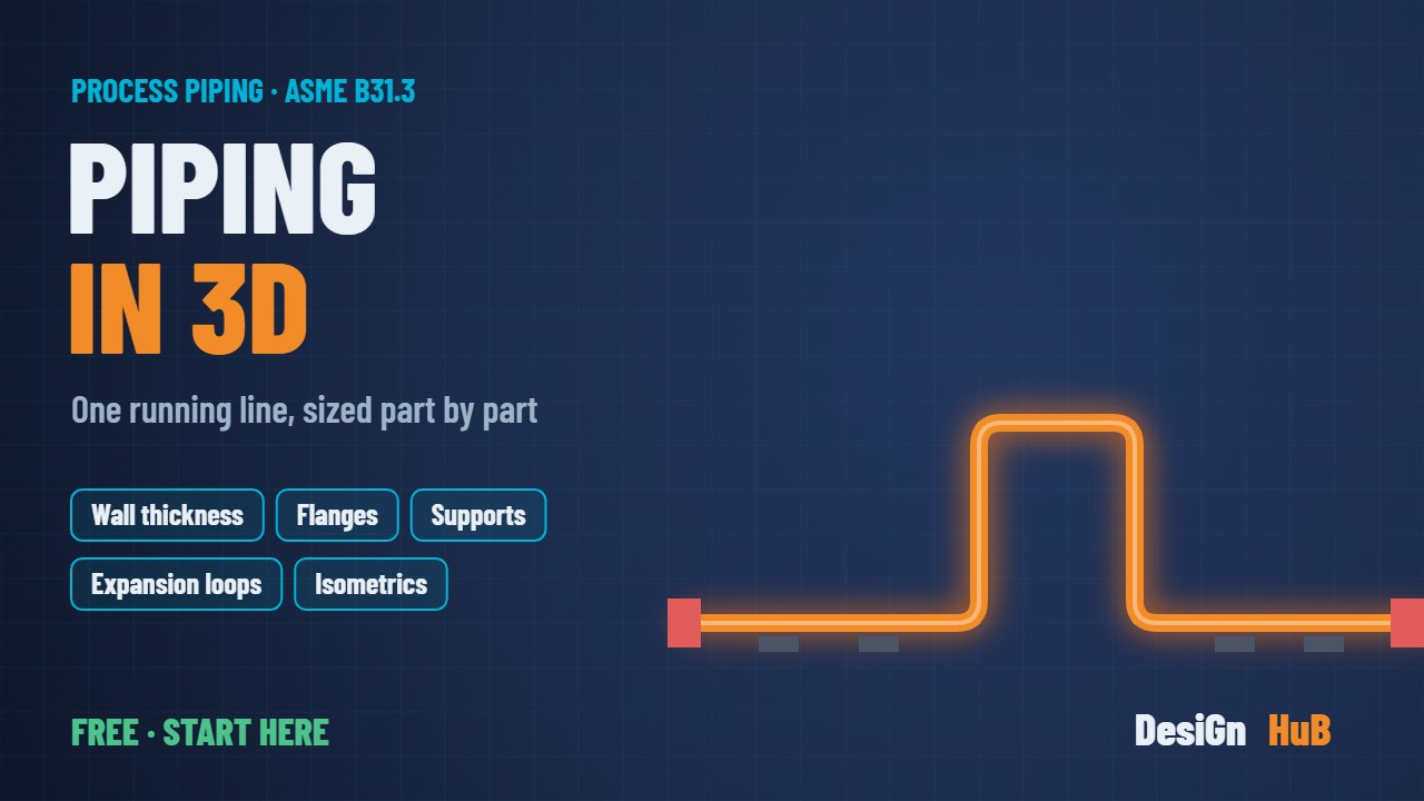
Piping design, made visible. Every part takes one real piping question and answers it with a hand calculation to ASME B31.3, animated in 3-D so you can see what the numbers mean: a pipe wall split into the millimetres that hold pressure, a hot line growing, a loop flexing.
One running example: line 6″-P-1001, 6″ Sch 40 A106 Gr B, from indirect heater H-100 to separator V-100 (the same V-100 as our Pressure Vessel, P&ID and Instrumentation series), design 15 barg / 180 °C.
- Preview: Why hot pipes need room to grow (thermal expansion, anchors, guides, expansion loop)
- Part 1: Pipe size, schedule & wall thickness (B36.10M, B31.3 304.1.2)
- Coming: flanges & the rating trap, the flange joint, valves, line sizing, supports & span, flexibility, nozzle loads, water hammer, 3-D model to isometric
Every number comes from a worked calculation, and every code value used is listed so you can check it against your own edition.
Course Content
Piping in 3D: the worked line (6″-P-1001)
Student Ratings & Reviews

No Review Yet
