How thick does a pressure vessel shell need to be? Under ASME Section VIII Division 1, the answer comes from one clause, UG-27, and four inputs: pressure, radius, allowable stress and joint efficiency. This guide works through a real-size example, a 1800 mm three-phase separator at 15 barg, from required thickness to plate selection, MAWP and hydrotest pressure. You can change every input in the live 3-D model below.
Try it: the pressure vessel shell lab
Drag the sliders and watch the required thickness, the ordered plate and the MAWP update. The shell colour shows how close the pressure is to MAWP. Press Run hydrotest to take the vessel to 1.3 × MAWP. This lab is part of Design Hub Labs, our set of interactive 3-D engineering simulations. You can also open it on its own page.
| Required t, circumferential stress · UG-27(c)(1) | |
| Required t, longitudinal stress · UG-27(c)(2) | |
| t + corrosion allowance | |
| Plate to order (next standard size) | |
| Shell MAWP, corroded · inverted UG-27 | |
| Hoop stress at the gauge pressure (corroded) | |
| Hydrotest ≈ 1.3 × MAWP · UG-99(b) |
The UG-27 shell thickness formula
A cylindrical shell under internal pressure carries two membrane stresses. Hoop (circumferential) stress tries to split the shell along its length, and longitudinal stress tries to pull it apart around its girth. Hoop stress is twice the longitudinal stress, so the circumferential formula almost always governs. UG-27(c) gives both:
Circumferential, UG-27(c)(1): t = P·R / (S·E − 0.6·P)
Longitudinal, UG-27(c)(2): t = P·R / (2·S·E + 0.4·P)
P = design pressure · R = inside radius in the corroded condition · S = allowable stress at design temperature (Section II Part D) · E = joint efficiency (UW-12)
Valid while t ≤ R/2 and P ≤ 0.385·S·E. Beyond that, use the thick-shell formulas in Mandatory Appendix 1-2.
Watch the sign in the denominator: it is −0.6P for the circumferential case. Several calculation sheets online use 0.4P here, which is the longitudinal (or spherical) form and gives a thinner, unconservative shell.
Design basis: separator V-100
| Item | Value | Source |
|---|---|---|
| Vessel | Horizontal three-phase separator, ID 1800 mm × T/T 6000 mm, 2:1 ellipsoidal heads | Process datasheet |
| Design pressure | 15 barg (1.5 MPa) + full vacuum | Part 1: design basis |
| Design temperature / MDMT | 120 °C / −29 °C | Process datasheet |
| Material | SA-516 Grade 70, S = 138 MPa at 120 °C | ASME II-D Table 1A (confirm against your edition) |
| Corrosion allowance | 3 mm | Process / materials |
| Joint efficiency, shell long seam | E = 0.85 (spot radiography) | UW-12, Table UW-12 |
Step 1: Use the corroded inside radius
UG-27 is applied in the corroded condition, at the end of the vessel’s life. Corrosion eats the inside surface, so the inside radius grows by the corrosion allowance:
R = ID/2 + CA = 1800/2 + 3 = 903 mm
S·E = 138 × 0.85 = 117.3 MPa · check: P = 1.5 MPa ≤ 0.385 × 117.3 = 45.2 MPa ✓
Step 2: Required thickness
t = 1.5 × 903 / (117.3 − 0.6 × 1.5) = 1354.5 / 116.4 = 11.64 mm
Longitudinal check: 1.5 × 903 / (2 × 117.3 + 0.4 × 1.5) = 5.76 mm → circumferential governs
Step 3: Add corrosion allowance and choose the plate
Now add the static head (UG-22). Full of liquid, the bottom of the shell sees about 15.18 barg, so the required thickness there is 1.518 × 903 / (117.3 − 0.6 × 1.518) = 11.78 mm. Add the corrosion allowance, 11.78 + 3 = 14.78 mm, and round up to the next standard plate: 16 mm (14 mm is too thin). The extra 1.22 mm is plate round-up. UG-16(c) lets you use plate with a mill undertolerance up to the smaller of 0.3 mm or 6 % at full design pressure. If your plate supplier’s tolerance is bigger, add it before rounding.
Step 4: MAWP, the pressure the shell can really take
You ordered more steel than required, so the shell can hold more than 15 barg. Invert UG-27 with the corroded thickness, 16 − 3 = 13 mm, to find the maximum allowable working pressure:
P = S·E·t / (R + 0.6·t) = 117.3 × 13 / (903 + 7.8) = 1.674 MPa = 16.74 barg
MAWP is stamped at the top of the vessel. The liquid head across the 1.8 m shell (about 0.17 bar for an oil and water mix of about 960 kg/m³) is subtracted: MAWP at top = 16.74 − 0.17 = 16.57 barg.
The whole vessel’s MAWP is the lowest of all its parts: shell, heads, nozzles and flanges. Here the 16 mm shell governs. The PSV is then set at or below MAWP, and in this example it is set at the 15 barg design pressure (see the PSV Design Series).
Step 5: Hydrotest pressure, UG-99(b)
Ptest = 1.3 × MAWP × (Stest / Sdesign) = 1.3 × 16.57 × (138/138) = 21.54 barg at the top
SA-516-70 has the same allowable stress at test temperature and at 120 °C, so the stress ratio is 1. The gauge at the bottom reads higher by the water head.
What full radiography buys you
Joint efficiency is a design choice, not a constant. With full radiography (E = 1.0) the required thickness drops to 9.88 mm, so 12.88 mm with CA, and the shell can be ordered in 14 mm plate. That saves about 540 kg of steel on the 6 m shell, against the cost of radiographing every long seam. Set E to 1.00 in the lab above to see it.
| Joint efficiency | Required t | t + CA | Plate |
|---|---|---|---|
| 0.85, spot RT | 11.64 mm | 14.64 mm | 16 mm |
| 1.00, full RT | 9.88 mm | 12.88 mm | 14 mm |
Don’t forget the heads (UG-32)
The 2:1 ellipsoidal heads use UG-32(d): t = P·D / (2·S·E − 0.2·P). With D = 1806 mm (corroded) and E = 1.0 for a seamless head, t = 1.5 × 1806 / (276 − 0.3) = 9.83 mm. Add 3 mm CA and allow about 10 % thinning during forming: 12.83 / 0.9 = 14.25 mm, so the heads are also ordered in 16 mm. Hemispherical and torispherical heads are compared in Part 3: the heads.
Five mistakes that fail design reviews
- Using 0.4P instead of 0.6P in the circumferential formula. That is the longitudinal or spherical form.
- Using the new (uncorroded) radius. UG-27 needs the corroded radius, R = ID/2 + CA.
- Forgetting static head. Liquid adds pressure at the bottom of the shell, and MAWP is stated at the top.
- Confusing design pressure with MAWP. Design pressure is what you ask for. MAWP is what the ordered steel can actually take.
- Taking E = 1.0 without full radiography, or using a seamless head’s E for a welded one. E must match the inspection you actually specify.
Watch the worked example


Design the whole vessel, not just the shell
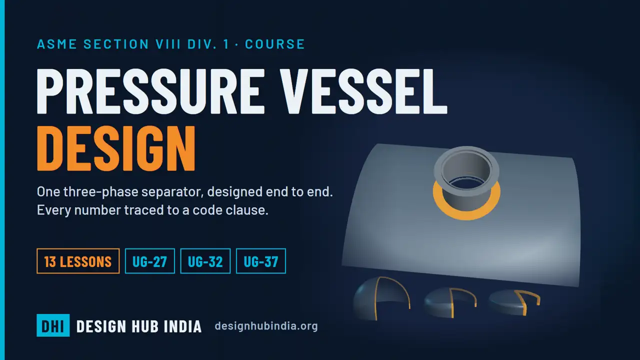
The Pressure Vessel Design course follows V-100 end to end: design basis, shell, heads, nozzle reinforcement, external pressure, MDMT and hydrotest. The first 5 lessons are free; the full course with certificate is $20.
Start the free lessons → ASME VIII Pressure Vessel Calculator Thick-wall (Lamé) calculatorFrequently asked questions
What is the formula for pressure vessel shell thickness?
Under ASME Section VIII Division 1, UG-27(c)(1) gives the required thickness of a cylindrical shell for hoop stress as t = P·R / (S·E − 0.6·P), using the corroded inside radius. Add the corrosion allowance and round up to a standard plate.
How do you calculate MAWP from shell thickness?
Invert UG-27: MAWP = S·E·t / (R + 0.6·t), with t the ordered thickness minus corrosion allowance. Then subtract the static head down to the top of the vessel, and take the lowest value of all the vessel’s parts. In the example, a 16 mm shell gives 16.74 barg, or 16.57 barg at the top.
What is the hydrotest pressure for an ASME VIII Div. 1 vessel?
UG-99(b) sets the minimum hydrostatic test pressure at 1.3 × MAWP × the lowest ratio of allowable stress at test temperature to allowable stress at design temperature. For the example vessel that is 21.54 barg at the top.
What joint efficiency should I use?
E comes from Table UW-12 and depends on the joint type and how much radiography you specify. For a double-welded butt joint it is 1.0 with full radiography, 0.85 with spot radiography and 0.70 with none. Seamless heads use E = 1.0.
When is UG-27 not valid?
UG-27 is a thin-shell formula. It applies while the thickness is no more than half the inside radius and the pressure is no more than 0.385·S·E. Thicker, higher-pressure shells use Mandatory Appendix 1-2. Try the thick-wall (Lamé) calculator for those.
References: ASME Boiler and Pressure Vessel Code, Section VIII Division 1: UG-16, UG-27, UG-32, UG-99, UW-12; Section II Part D, Table 1A. Allowable stresses and clause numbers change between editions, so always check your contract edition. Related guides: The three lives of a pressure vessel · ASME B31.3 pipe wall thickness · PSV sizing to API 520.
